I've gotten a few questions in email about the process we used to make our wing molds, so I thought I'd put together a quickie refresher course to what we've been doing and what we've done.
The first step is to make wing plugs. The plugs are just collections of garbage in the shape of what you want to make. In our case, of course, what we want to make are big, smooth, shiny sailplane wings. So our plugs are big, smooth, and shiny.
Here's a cross-section of our sailplane wing plug:
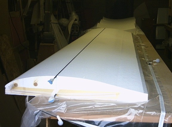
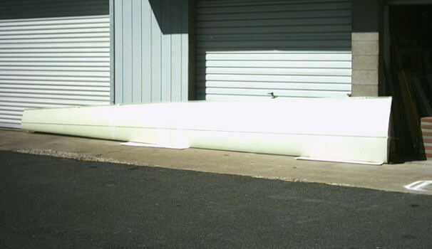
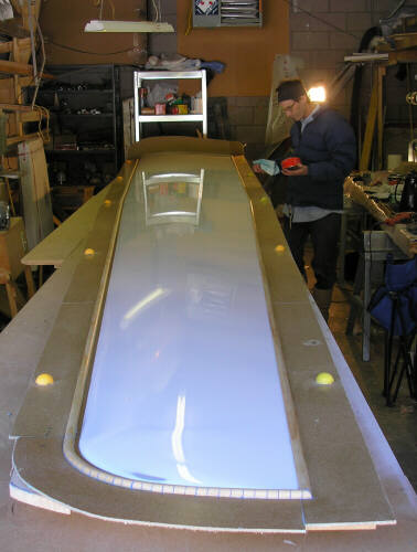
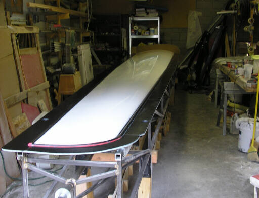
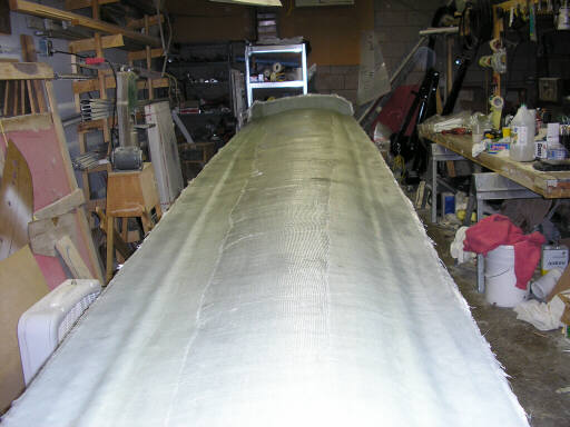
And here's a couple of photos of our wing plugs in various stages:
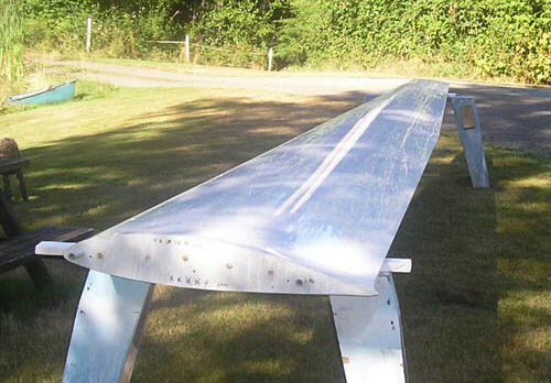
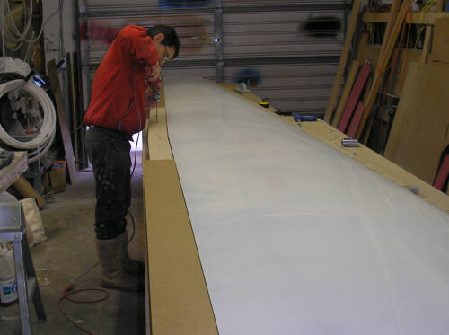
Next, we take our wing plug and arrange it over a flat, untwisted work surface using alignment cradles and whatnot so that it doesn't rock or move around. Then we arrange flange boards along the leading and trailing edge to form the flanges of our mold. We also add half-round mouldings (usually 11/16" mouldings from the local hardware store) to the leading and trailing edge to form trenches in the mold where extra bonding resin can squeeze out into when we go to bond wing skins together. Here, the plug is shown upside down because I like to start wing molding on the bottom surface, so we do the less-critical surface first.
Here are some photos of that part of the process. This closeup shows one of the wedge adjusters I made to position the flange board at the right height for the leading and trailing edge. Behind it you can see the styrofoam shuck (left over from making the foam cores for the wing plugs) we're using to cradle the wing plug.
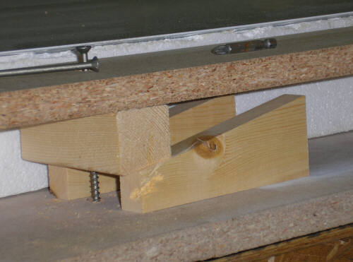
Here I'm inserting one of the screws that secures the wedge adjuster. This photo shows how we're using 3/4" fiberboard for a foundation, and adding 1/8" masonite for the molding surface. The masonite gives us a nice surface, and doesn't require any surface treatment except waxing.
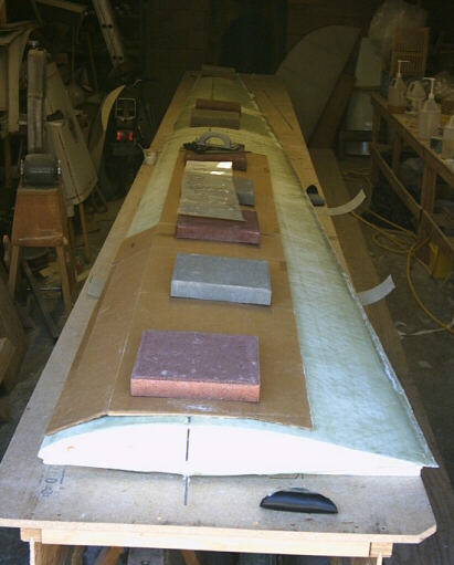
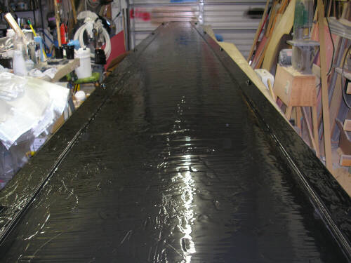
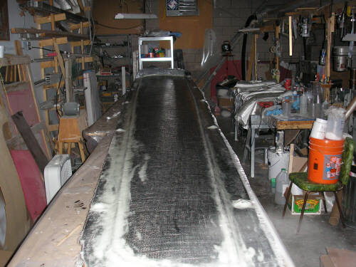
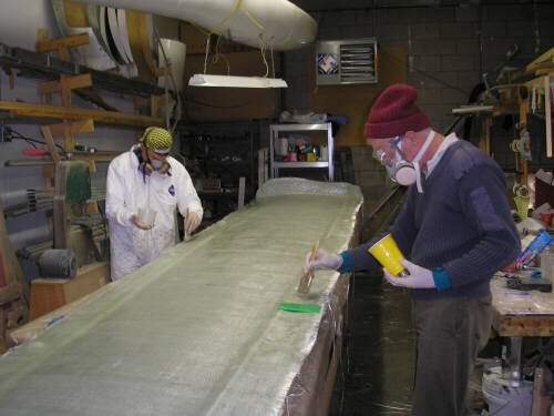
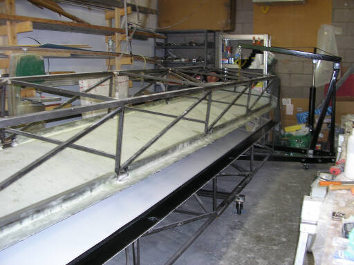
When we're satisfied with the wing plug and flange features, we wax the whole thing up with five coats of mold release (I use TR-104 wax), brush on a coat of TC-1611 black tooling resin, and then do a thick, messy fiberglass layup over the tooling coat. We use lots of shmoo (a mix of microballoons, cabocil, flox, and epoxy) in the tight corners where the fiberglass cloth doesn't like to drape down into. Here, the mold shell layup is shown in green.
More photos of this stage:
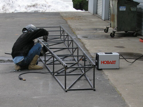
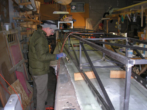
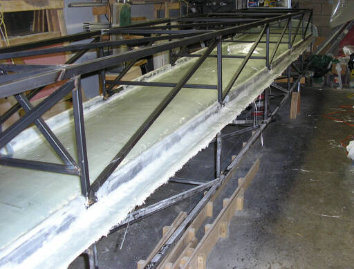
After the mold shell layup has cured, we glue on the steel stiffening truss using fiberglass tapes along the truss longerons.
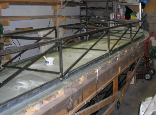
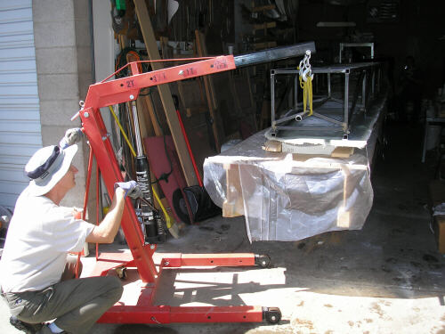
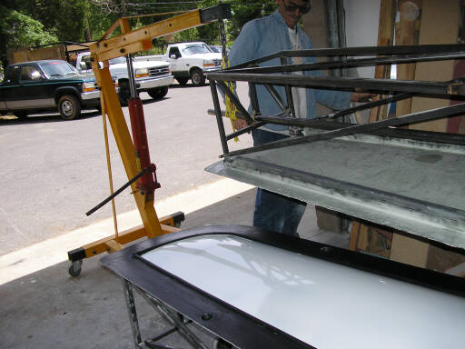
After the truss bonding tapes have cured, we use a pair of engine hoists to roll the whole thing over. Then we strip away the masonite boards that formed the flangs, and dig the half-round trench strips out of the squeeze-out trenches. We replace the half-rounds with full-round material. I've found that 0.710" diameter black drip irrigation tubing fits the trench made by the 11/16" moulding just fine.
Then we apply more tooling resin, then another big messy fiberglass layup. We're looking for somewhere between 3/16" and 1/4" of thickness, so we use about 8 layers of 18 oz roving. That heavy roving doesn't like to get into the corners, so we usually do a few perimeter plies with finer cloth such as 7725 or whatever is left over from other projects.
And then we bond on the stiffening truss for the upper mold shell.
Once the upper truss bond has cured, we can crack open the molds and liberate the wing plug and the trench tubes. This job is usually quite a chore involving many small wedges, but it's never been particulary heinous. I've found that it helps to bang lightly on the mold shell with a rubber mallet to free it from the wing plug surface.
That's the basics, but of course there's always a lot more to it: the devil is in the details. Before you can actually make wings in molds like these you need tooling for a bunch of interior parts - things like locators for hinges and control features and spar features, stuff like that.
Later this week I'll try to get around to doing sketches of what we're doing at the shop right now, which is making the mold features for the joggle where the upper and lower wing skins get bonded together along the leading edge.
page updated 8 August 2006 all text and graphics copyright (c) 2006 HP Aircraft,
LLC