As I previously scheduled, last weekend (16 and 17 August 2008) Brigitta and I unbagged the shear webs, trimmed and fitted them, and then bonded them in place in the lower horizontal stabilizer skin. We didn't put in the hinge points, though, I decided to defer that until I've finished the elevator. But we did get everything in place to bond the stabilizer skins together next weekend so I can bring a kit-finished stabilizer to Tehachapi for the 2008 ESA Western Workshop.
I think that the next time we do these stabilizer skins I will omit the leading edge joggle from the initial vacuum-bagged layup, and add them in a secondary operation. The joggle makes the layup more awkward, the bagging more difficult, and generally makes a high-pressure operation a little more stressful.
Another thing, having made these horizontal stabilizer skins from carbon I have to say that I really like working with carbon. It wets out fairly easily, it drapes nice, and best of all it takes a lot less of it than fiberglass to do the job. Less cloth means less epoxy, and more importantly less time spent fussing with fuzz and goo. Less time means we can get in, get it done, and get the hell out of there eariler and go do something fun.
So, yeah, I be liking the carbon. I can definitely see using more of this stuff in the future.
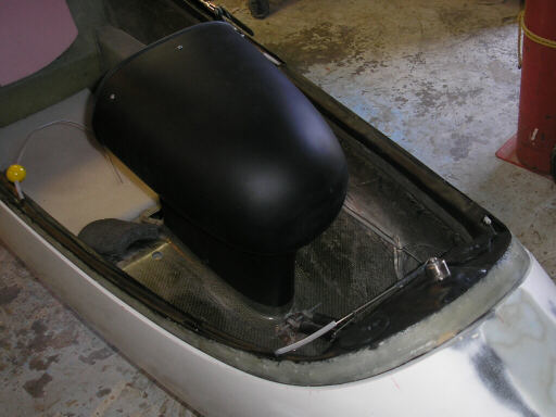
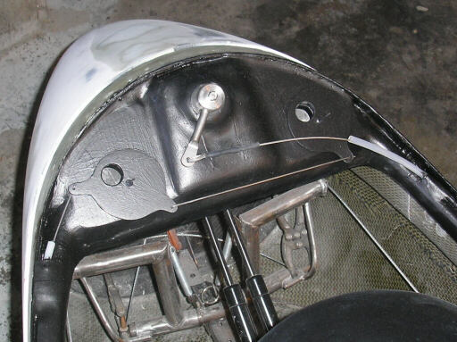
Up at Brad's shop he's finishing up his canopy pivot and jettison parts, and also the ventilation regulator, and he's painted all of those parts a nice even black.
And now the photos:
Unbagging the shear webs. I like to reuse these bags where practical, and the easiest way to separate them from the parts is to connect the vacuum taps to high pressure air and inflate them like balloons.
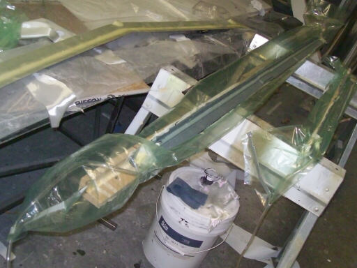
Here's the shear webs trial-fitted into the spider that aligns them with the lower skin. Omitted is an hour or so of rough trimming the edges with tin snips, sanding the edges smooth, and locating and boring the three holes for the main attachment fitting. The tool set sitting on the mold flange near the upper right corner of the photo is a transfer punch set from Harbor Freight, graduated in 1/64" increments. It's probably been the best $10 tool I've ever gotten from Harbor Freight. Here I used it to center-punch the main attach fitting holes.
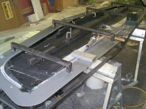
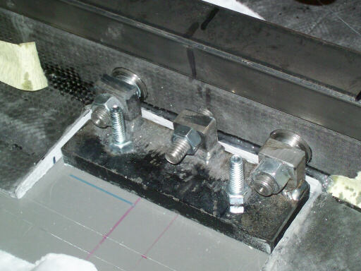
Here's all that stuff going on at the plane of symmetry. At the bottom is the mold fixture that locates the attachment sockets and tightening stud. At the top, the two white dots are the locations of the 3/16" holes for the bolts that secure the forward attach fitting.
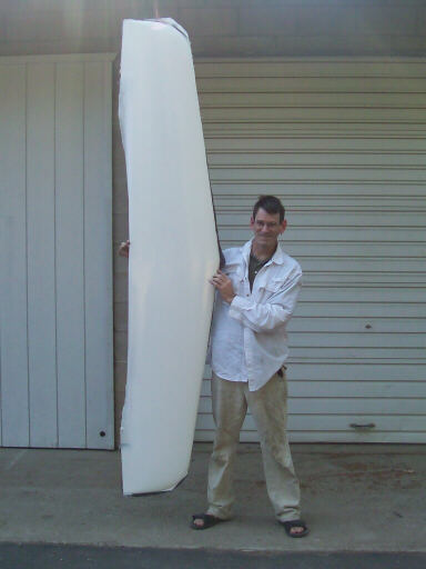
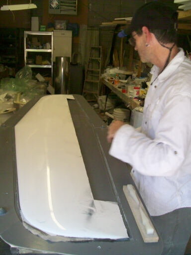
The obligatory "See what I made!" photo with the upper skin. We tried to weigh it on my epoxy scale, but it exceeded the scale's 1.2 kg capacity so I didn't get a good reading. However, I know we're on track to make a stabilizer that significantly undershoots the fiberglass example I made earlier. That part came in at about 13 lbs all told, and for this carbon example I think we're looking at 8-9 lbs or so. That fiberglass part was very similar in weight to that of the ASW20, but I think we can and ought to try for better.
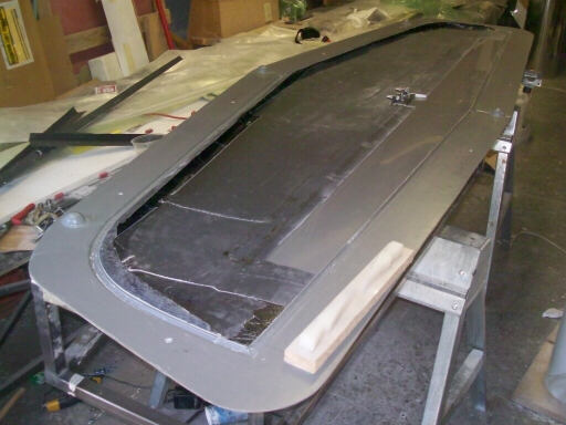
The lower skin cleaned off a bit and dropped back in the mold.
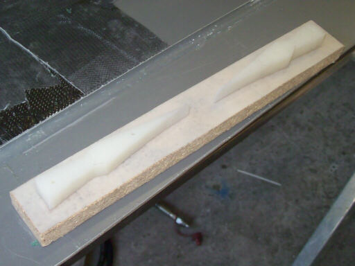
This doodad is a revised mold for the "lost arrow ribs" that close out the outboard ends of the elevator cutout. Like the earlier lost arrow mold it is made of bandsawn material to form a male mandrel for a drape-molded part. However, for this more permanent version I made the mandrels out of 5/8" nylon. The platform is 3/4" fiberboard with a layer of mylar glued onto it. While I was getting started on bonding in the shear webs, Brigitta laid up and bagged a set of these ribs; they'll be ready when we go to close the stabilizer skins together.
And with the upper skin placed on it for a trial fit. The black stuff near the corner of the elevator cutout is carbon dust from the rough trimming of the cutout.
The lower skin after bonding in the shear webs. The white patches are polyester peel ply.
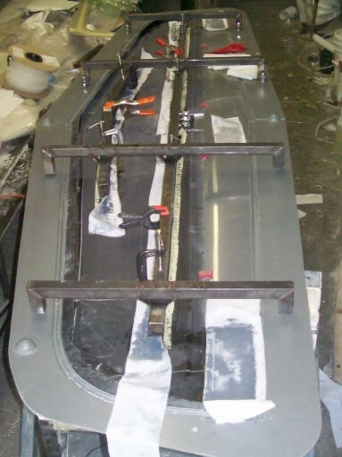
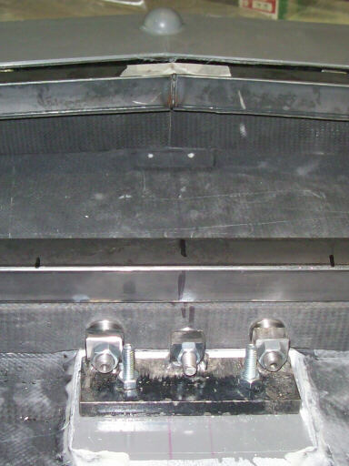
The attachment locating fixture after the bonding operation. The sockets are stainless steel parts that are getting bonded into holes in the shear web. In that area the shear web is reinforced with a piece of Garolite. The stud in the center (actually a fully-threaded stainless steel bolt installed from the front) is also getting bonded in; it is installed in a tapped hole in the Garolite and its head, like the front of the mounting sockets, is captured with several layers of carbon cloth. I can't remember what the blue line on the mold is, but the red lines are each 3/8" each side of the plane of symmetry. The white lines are separation lines for the forward edge of the elevator and for the trim line at the aft edge of the stabilizer skin.
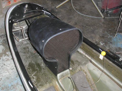
Here's what Brad's cockpit is looking like these days. It certainly is starting to look like a real sailplane.
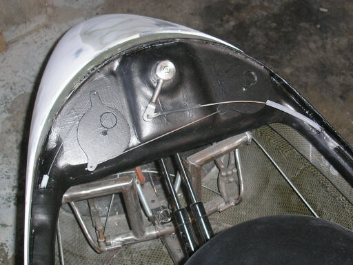
Here's Brad's ventilation regulators in open and closed positions. Pretty slick.
Homebuilt aviation is not for folks who don't try things at home.
page updated 19 August 2008 all text and graphics copyright (c) 2008 HP Aircraft,
LLC